Assembling the RAFM Imp
The Imp is a great little APC/Scout Car from RAFM's 15mm Science Fiction line. I picked up a couple of these during a sale RAFM was having, and it took me a while to get the first one assembled as, apart from the picture on the RAFM website, there's no information on how these models go together.
 When I came to assemble the second Imp, I thought I might document the process in case anyone else was sitting at their modeling desk with an Imp in front of them and wondering where to begin.
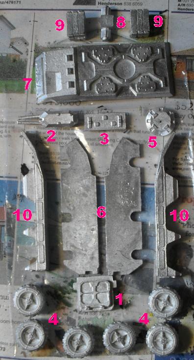
- 1). Rear Hatch to the vehicle. This also forms the short rear side of the basic vehicle box shape.
- 2). Dual Autocannon turret - one of two possible weapon loads.
- 3). Lower Front panel - this is the reverse angle panel, below the nose of the vehicle. This piece forms the front short side of the basic vehicle box shape.
- 4). Wheels - this is a six-wheeled vehicle.
- 5). Ring mount for the upper deck weapon loads.
- 6). Two structure frames. These frames form the long sides of the basic vehicle box shape. The frames support the upper deck, and provide mounting points for the vehicle's wheels. The frames also provide anchor points for the Rear Hatch and the Lower Front panel.
- 7). Upper deck of the vehicle.
- 8). Mount for the two missile boxes that make up the second possible weapon load.
- 9). Missile boxes for second possible upper deck weapon load.
- 10). Mudguards. One for each side of the vehicle.
Step 1
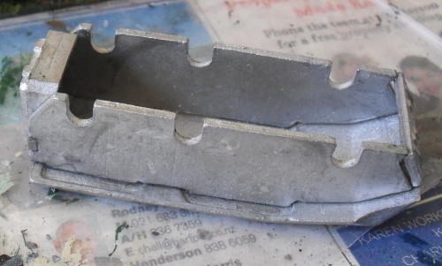
I discovered, after much swearing and sticking of fingers together that, once the pieces had been cleaned up, the best plan was to build the basic box shape of the vehicle. The two structure frames (no. 6) form the long sides of the box, while the Rear Hatch (no. 1) and the Lower Front panel (no. 3) form the two short sides of the box.
For some reason, I seemed to acquire an extra set of thumbs when it came to glueing these four pieces together, but eventually they took. One thing to remember, at this point, is that you are also aiming for the best fit with the upper deck. The two lugs visible on the underside of the upper deck will, ideally, fit on the outside of the structure frames, centering the box shape under the upper deck. The structure frames do flex, which gives you a little wiggle room, but too much flexing can pop the glue joints.
Step 2
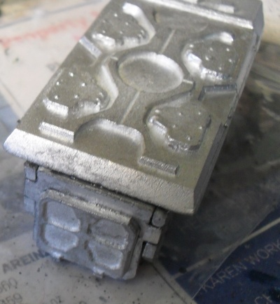
I mentioned that the structure frames have a degree of flexibility which allows you a little latitude when fitting the basic box shape under the upper deck. The upper deck is also flexible, and can be carefully shaped for a snugger fit by some gentle pressure.
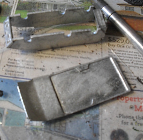
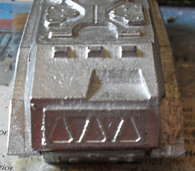
 When all the glue is dry, you should end up with a fairly strong box, like this. The addition of the upper deck cross-braces the basic box shape, giving it more rigidity. At this point, don't be too concerned about any gaps at the joins between the various plates. These can be filled with PVA and painted over.
The top deck extends beyond the sides of the basic box shape, so when seating it upon the box, you need to try and balance the extent of the overhangs - these will help intergrate the mudguards into the finished model.
 |
 |
 |
 Having completed the basic box, we're probably through the sweariest part of the assembly process. The mudguards (no. 10) are next up.
Step 3
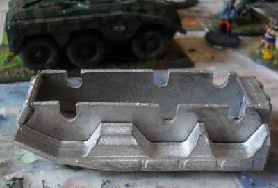 The mudguards run along each side of the vehicle, pretty much matching up with the length of the upper deck. The most important place - where they do have to line up - is at the rear of the upper deck, where the upper deck meets the rear hatch. The rear of the mudguards have tail light assemblies moulded into them and so there is little room to file them back if they don't fit correctly.
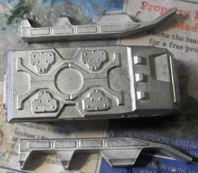
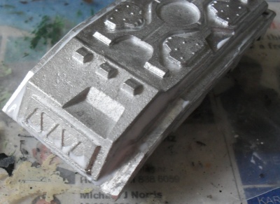
When comparing the completed model, to the rear of the picture to right, with the one I am assembling, you can see that the addition of the mudguards to the sides of the vehicle in turn creates the wheel wells. I did think of doing a dry fit before gluing the mudguards on, but only after I had glued the mudguards on. Fortunately, the wheel wells are sufficiently wide that you have a little wiggle room when fitting the wheels.
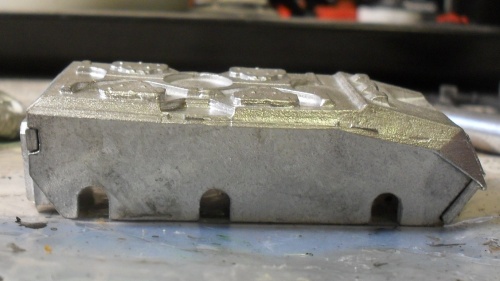
 Now, I indicated above that you needed to align the mudguards with the rear of the vehicle. In this photo, to left, you can see that the right hand mudguard protrudes slightly beyond the front of the vehicle. I was able to clip the excess back and then file everything off neatly. If the overhang had been at the back, I would have had to destroy the tail light assembly to even the two mudguards up.
 Once I had finshed cleaning up the mudguards, I sealed up the gaps between the upper deck and the mudguards with PVA glue. I could have used some sort of filler or putty, but PVA - or white glue - is sufficiently viscous that it will fill most gaps, and can be easily smoothed back as it dries. Once dried, it is easy to paint.
Step 4
With the body of the vehicle sealed and complete, we turn to the wheels.
The Imp uses a groove and spigot method for mounting the wheels on the vehicle. This allows the wheels to be positioned independently, relative to each other, and within a small vertical range. So, lots of fun for people modelling mountainous terrain - not so much fun for people like me who have to line things up by eye.
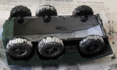 The spigots on the wheels were a relatively snug fit in the grooves in the structure frames. Once I undercoated the wheel wells and the backs of the wheels, the two layers of paint made the fit very tight. A little wiggling and forcing enabled me to position the wheels in an approximately level fashion.
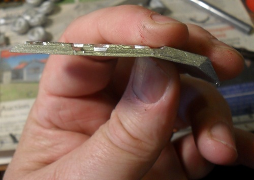
 Eventually, I discovered that as long as about three-quarters of the spigot was below the edge of the structure frame, the wheels were both even, and fitted well within the wheel well.
Step 5
I'm not a big fan of missiles. The arming options for the Imp were either a dual-missile box mount or an dual-autocannon mount so I went with the dual-autocannons.
The dual-autocannons (no. 2) glue onto the ring mount (no. 5) to form a nice little remote turret. I decided not to attach the ring mount of the remote turret to the upper deck as I wanted to be able to pose the turret.
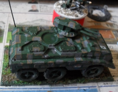 Painting then commenced. I decided to attempt a faux urban camouflage pattern, modelled on an effect I had seen achieved with stencils. It didn't come out
 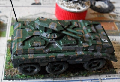 too badly, I think. I coated the underside of the turret ring mount, and the receptor on the upper deck, with GW 'ardcoat varnish to give the paint under the revolving turret a little protection.
To finish of the model, I eventually based it on a piece of plastic card for both strength and appearance. A hole for the aerial was drilled into the left rear mudguard and the aerial is made from a bit of wire. Just recently, I've started using nylon brush bristles for aerials and these, I think, give a better, and less leathal on your fingers, result.
The card decal on the front of the vehicle is from a set of World War II vehicle decals, while the badge of the side is from a set of Hammer's Slammers decals.
All in all, a very nice little model that looks excellent when completed.
| Back to Model Making |